

Astonishingly fast MDS remote response using System 1 20.1 in Argentina

Industry: Pulp and Paper
Application: In house Power Generation
Solution: Remote Diagnostic Services - System 1 20.1
The Latin America MDS team was contacted on a Friday night, seeking for immediate support in getting the main steam turbine generator TG2 back online. After a non-vibration-related trip, the customer (Papel Misionero, ARCOR GROUP) had not been able to start the unit, due to a trip event on high vibration at turbine bearings near nominal speed.
On Thursday July 9th a short circuit in the 4MW-motor driving the high-density refining unit caused an electrical protection trip on unit TG2. During the process of bringing back online other areas of the plant, the auxiliary power unit TG 1 also tripped, causing the turning gear system on TG2 to shutdown, which had been operating for only two hours. After having solved the short circuit issue, the turning gear system on TG2 is turned on Friday July 10th, and the steam turbine generator is ready to start at 21hs that day. However, the unit tripped on high vibration at turbine non-drive end bearing when reaching 96% of full speed. After four unsuccessful startup attempts, Bently Nevada MDS Services was contacted at 11pm that night.
Due to COVID19 travel restrictions in Argentina (the plant is 1000Km away), no Field Engineer or even any piece of equipment could get to the site at all. The only hardware available on site was the existing Bently Nevada 3500 protection system. Given the urgency to troubleshoot the vibration problem, as well as the adverse logistics, there was only one option left.
With the help of the customer´s IT department, System 1 20.1 was installed and licensed remotely in a laptop connected to the 3500 rack. The laptop was then remotely accessed through Teamviewer software, and by Saturday July 11st at 4 pm, the unit was ready to start up again, this time with Latin America MDS Technical Leader looking at System 1 20.1 in real time.
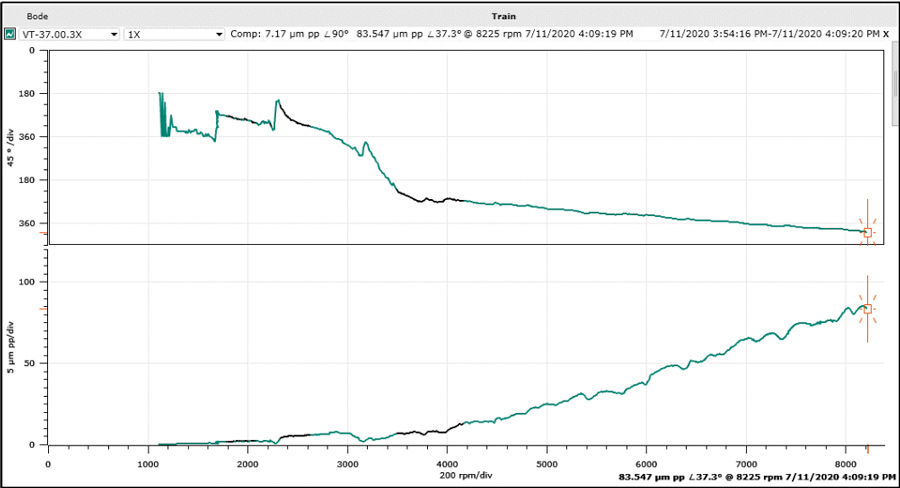
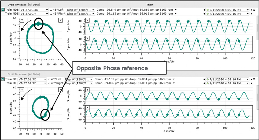
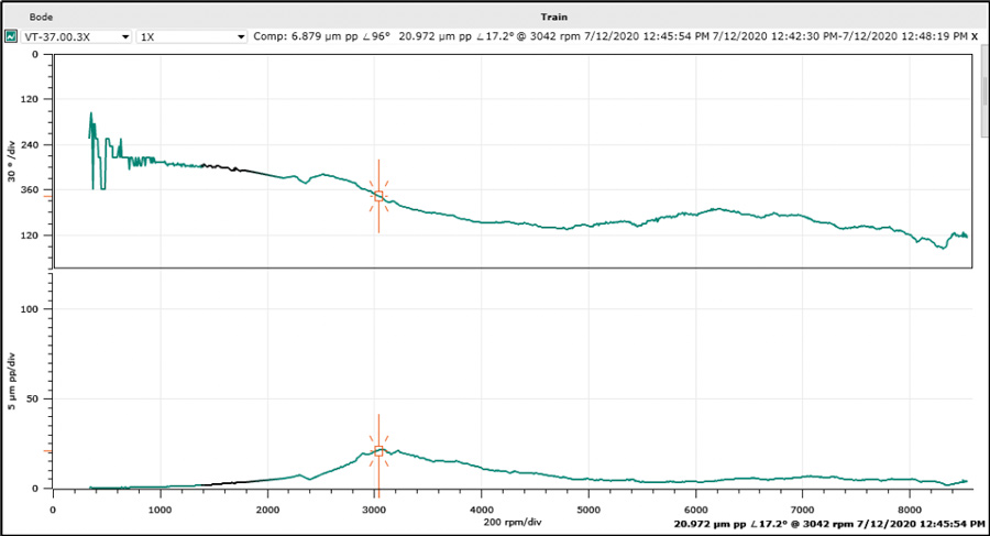
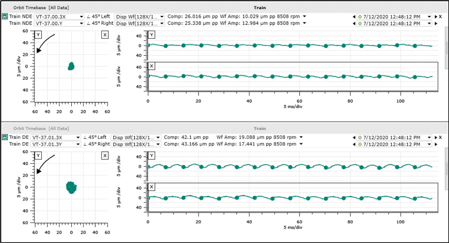
Plot # 1 shows a rapid increase in synchronous amplitudes above 5000 rpm on the turbine non-drive end bearing. Along with the increase in amplitude, direct orbits at both bearings presented a clearly circular shape, as shown on Plot # 2. Also, as indicated in Plot # 2, the phase reference or keyphasor dots at both orbits were located opposite each other, indicating second mode vibration.
Even though this behavior seemed to indicate elevated residual unbalance on the second mode, the conditions in which these symptoms manifested made it impossible for the rotor to develop such an unbalance condition while operating in turning gear (vibration amplitudes had been significantly lower before the trip event). Additionally, a bow due to lack of turning gear would have caused high “in phase” vibration for the first mode, which was not observed.
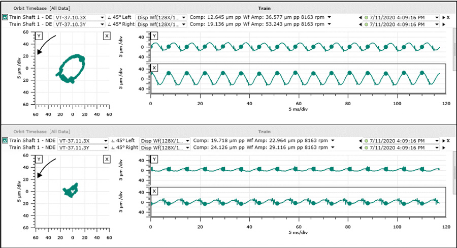
Given the relatively high synchronous amplitudes recorded also at the pinion drive end bearing (see plot # 3), the coupling between turbine and gearbox was believed to be related to the observed behavior.
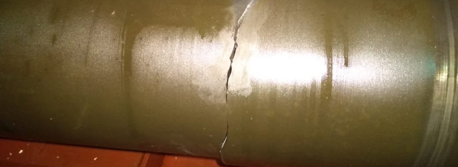
That same day after the new trip, the coupling guard was removed, exposing a significant circumferential crack in the spool piece, shown in picture # 1. A preliminary analysis of the failure indicated that, during the two hours with no turning gear operation, the casing contraction during cooldown had applied excessive radial load on the coupling, intensive enough to initiate the crack or enable the propagation of an existing smaller one. The crack had induced a bow in this coupling component, which had affected the turbine rotor second mode response at speeds above 5000 rpm.
The damaged spool piece was replaced, and the unit was ready to start up on Sunday July 12nd at noon. Plot # 4 shows a smooth synchronous response in the whole speed range, with amplitudes below 25 µm pp (1 mil pp). Plot # 5 shows the compensated direct orbits for both turbine bearings once the unit reached full speed (8500 rpm). Once at full speed, load was gradually increased reaching normal demand by Monday 13th.
In a COVID19 environment where no field engineer or data acquisition equipment could be deployed on site, a combination of Machinery Diagnostics expertise and System 1 20.1, Bently’s latest Asset Condition Monitoring platform, enabled remote troubleshooting of a vibration problem in a customer´s critical rotating equipment in record time. The customer went from having a critical piece of machinery down and no vibration data, to having Machinery diagnostics support in less than one day, and from having a vibration problem of unknown origin to addressing the root cause and implementing the solution in only two days.
Copyright 2019 Baker Hughes Company. All rights reserved. 베이커휴즈는 이 정보를 일반적인 정보 목적으로 ‘있는 그대로’ 제공합니다. 베이커휴즈는 정보의 정확성 또는 완전성에 대해 어떠한 진술도 하지 않으며, 상업성 및 특정 목적 또는 사용에 대한 적합성을 포함하여 법률이 허용하는 한도 내에서 구체적, 묵시적 또는 구두로 어떠한 종류의 보증도 하지 않습니다. 이에 의하여 베이커휴즈는 청구가 계약, 불법 행위 또는 기타 방식으로 주장되는지 여부에 관계없이 직접적, 간접적, 결과적 또는 특별 손해, 이익 손실 청구 또는 정보 사용으로 인해 발생하는 제삼자 청구에 대해 일체의 책임을 지지 않습니다. 베이커휴즈는 통지 또는 의무 없이 언제든지 본 문서에 명시된 사양 및 기능을 변경하거나 설명된 제품의 제공을 중단할 수 있는 권리를 보유합니다. 최신 정보는 베이커휴즈 담당자에게 문의하십시오. 베이커휴즈 로고, 벤틀리 네바다 로고, System 1은 Baker Hughes Company의 상표입니다.