Utilizing Compton Backscatter Technique for NDT
The Compton back scatter technique, see section 2.6, benefited from the introduction of computer technology into NDT equipment, just as most other methods discussed in this chapter.
It is now an accepted NDT-technique for plastics and light metals [2].
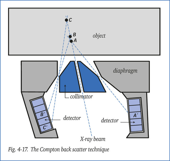
The scanner comprises an X-ray tube and a detector consisting of a number of elements as illustrated in figure 4-17. A collimator reduces the beam of rays to 0.5 mm in diameter, so that it cannot irradiate the detectors directly.
When a photon and an electron collide in the material, the primary X-radiation is scattered as somewhat softer radiation in all directions, and thus partly also back from the material to the scanner. This secondary radiation is then caught by the detector through a specially formed diaphragm, see figure 4-17.
The detector is made up of 20 or more detector elements marked A’, B’, C’ etc. each of which measures the quantity of back scattered radiation from a certain depth (A, B, C) in the object, as figure 4-17 shows. Each sensor element is, say, focussed on a certain depth. The cylindrical scanner measures only 7 x 7 cm and scans the
object in a grid. By linking the scanning system with a data processor, a comprehensive “Compton image” of the object develops and any
possible defects in it. This method has the advantage that an object needs to be accessible from one side only. It is for instance frequently
applied to honeycomb constructions and composite materials and has a penetration depth of approx. 50 mm. The method is (still) fairly slow; scanning a 50 cm2 surface takes approximately 5 minutes. An added advantage, however, is that the depth position of defects becomes known immediately as a result of the “quasi-focussing” of each individual detector element.