

Radiographic Techniques for Small Diameter Pipe Welds
For pipe welds, the single wall-single image technique (SW-SI), or if this is not feasible, the double wall-single image technique (DW-SI) is to be applied. For small diameter pipes this alternative is not really practical, as a disproportionate number of double wall-single image
exposures needs to be made due to the limited effective film length (see section). In such a case the double wall-double image technique should be used (DW-DI). Normally, the DW-DI technique is only applied on diameters <75 mm and wall thickness of <8 mm. Both, the weld on the source side and film side of the pipe are simultaneously interpreted.
Two more DW-DI techniques are suitable for small diameter pipes:
- the elliptical technique and
- the perpendicular technique

Elliptical technique
The elliptical technique, as illustrated in figure 2-18, is the preferred technique, but should
only be applied if the following conditions are met:
- external diameter (De) is <100 mm (in practice 75 mm)
- wall thickness (t) is <8 mm
- weld width < De /4
The number of exposures is determined by the relation between wall thickness (t) and
diameter (De). If t / De is < 0.12, two images - rotated 90° in relation to each other - are
sufficient for 100 % coverage. If t / De is equal to or bigger than 0.12, three exposures -
rotated 60 or 120° in relation to each other (i.e. equally divided over the circumference) -
is considered to be a 100 % examination.
When using the elliptical exposure technique, the images of the weld on the source side
and on the film side are shown separately, next to each other. The distance between two
weld images has to be approximately one weld width. This requires a certain amount of
source offset (V), relative to the perpendicular through the weld. The offset can be calcu-
lated with the following formula :

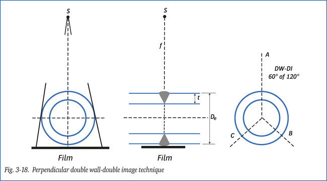
Perpendicular technique
Alternatively, the perpendicular technique can be used if the elliptical technique is not
practical, (see fig. 3-18). This is the case when, for instance, pipes of different wall thick-
ness are joined or a pipe is joined to a 45 °/ 90 ° bend.
Three exposures equally divided over the circumference are sufficient for 100% coverage.