What are the different types of ultrasonic probes?
The ultrasonic testing of materials cannot be carried out without the probes i. e. an instrument which generates sound waves. Such probes can be used as generators and receivers of sound waves and therefore they are of decisive importance in the testing system. They have decided influence on the output and Input signals. In order to locate a certain reflector and determine its size the specific characteristics of the sound source and the sound receiver must be previously known and are to be taken into consideration. The types of probes are every bit as varied as the types of specimens and the kinds of reflectors to be detected. There are probes for different types of materials and in different sizes, for direct contact with the specimen and for the immersion technique, for normal and inclined beaming, for short or long pulses. For the generation and reception of sound waves the pulse-sound technique uses almost exculsively piezo-electric plates (transformers) made from various ceramic materials such as barium titanate, lead-metaniobate, lead-zirconate etc. These plates are caused to oscillate mechanically by means of short electrical pulses. A damping element on the back of the transducer (and also coupling the probe to the test specimen) dampens the oscillations of the piezoelectric plate and that is how the ultrasonic pulse is formed (fig. 8). If the damping is weak the pulse is long and its frequency spectrum is narrow-band it is close to the resonant frequency of the piezoelectric plate. Heavy damping produces short broad band pulses as shown in fig. 9. These very short pulses offer a high resolution and make it possible to carry out accurate transit time measurements.
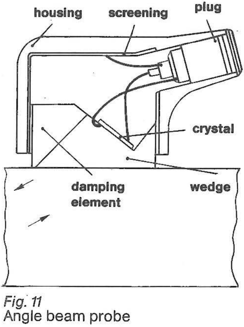
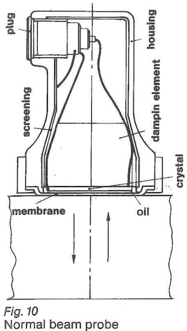
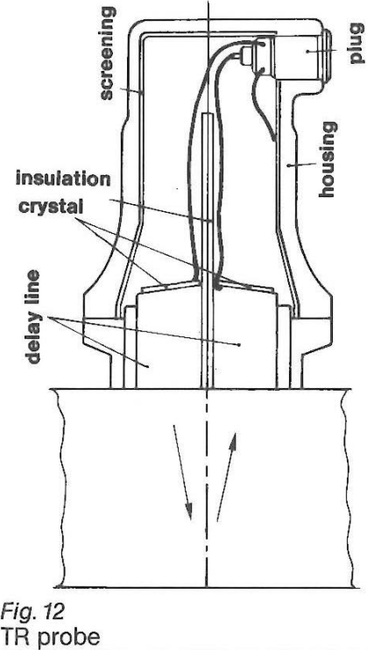
Probes which radiate their sound waves perpendicularly to the specimen surface are known as normal beam probes and probes which radiate their sound beams at an angle are known as angle beam probes (fig. 10, 11). Probes wich have separate elements for the transmitting and receiving functions are called (somewhat confusingly — for others do it too!) transmitterreceiver (TR) probes (fig.12).
Each probe generates a sound pulse in the test specimen corresponding to figs. 8 or 9. However the oscillation does not have to be absolutely in this form an the screen. Rectification and smoothing in the receiving component can cause a pulse form to appear an the screen which has not very much similaritiy to the sound pulse in the test specimen (screen cosmetics. fig. 13).
This type of screen cosmetics has the disadvantage that information regarding the condition of the best specimen which was contained in the original pulse as per figs. 8 and 9 is more or less lost.


