Global access to advanced radiographic and CT solutions
Waygate Technologies offers worldwide access to advanced radiography and computer tomography (CT) solutions, ensuring precision and reliability for non-destructive testing (NDT). Our systems are designed to provide peace of mind, helping industries maintain the highest safety standards while optimizing production efficiency.
With the broadest range of X-ray and CT technologies available, Waygate Technologies supports diverse industrial needs. Our solutions include conventional mobile film-based X-ray, computed and digital X-ray (CR and DR), as well as 2D and 3D CT systems. These innovations empower you to perform inspections with unmatched accuracy and speed.
You can also count on our support for our X-ray solutions. Our robust radiographic and tomographic solutions seamlessly integrate into your production environments. Whether you're conducting complex inspections or routine testing, our efficient, reliable systems help reduce costs and save time, allowing you to produce safer, more reliable equipment at every stage of the manufacturing process.

What we do?
We offer more premium non-destructive testing solutions than any other NDT brand.
A wide range of 3D computed tomography (CT) and 2D solutions for numerous inspection applications, from sub-micron resolution nano-CT and precision measurement tasks in the lab, to high energy CT with linear accelerators for large samples with high absorption, to high throughput CT inspections in production.
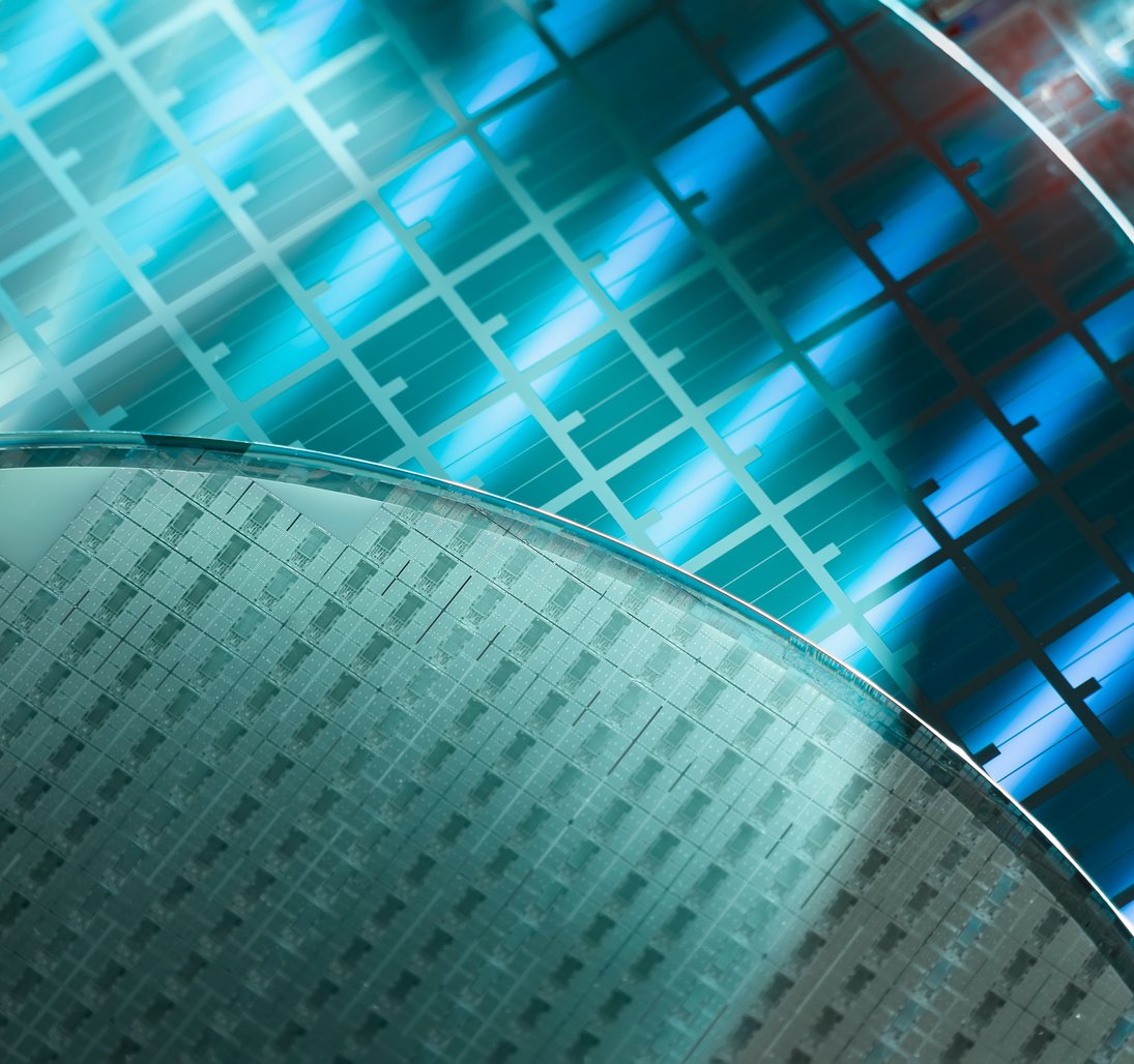
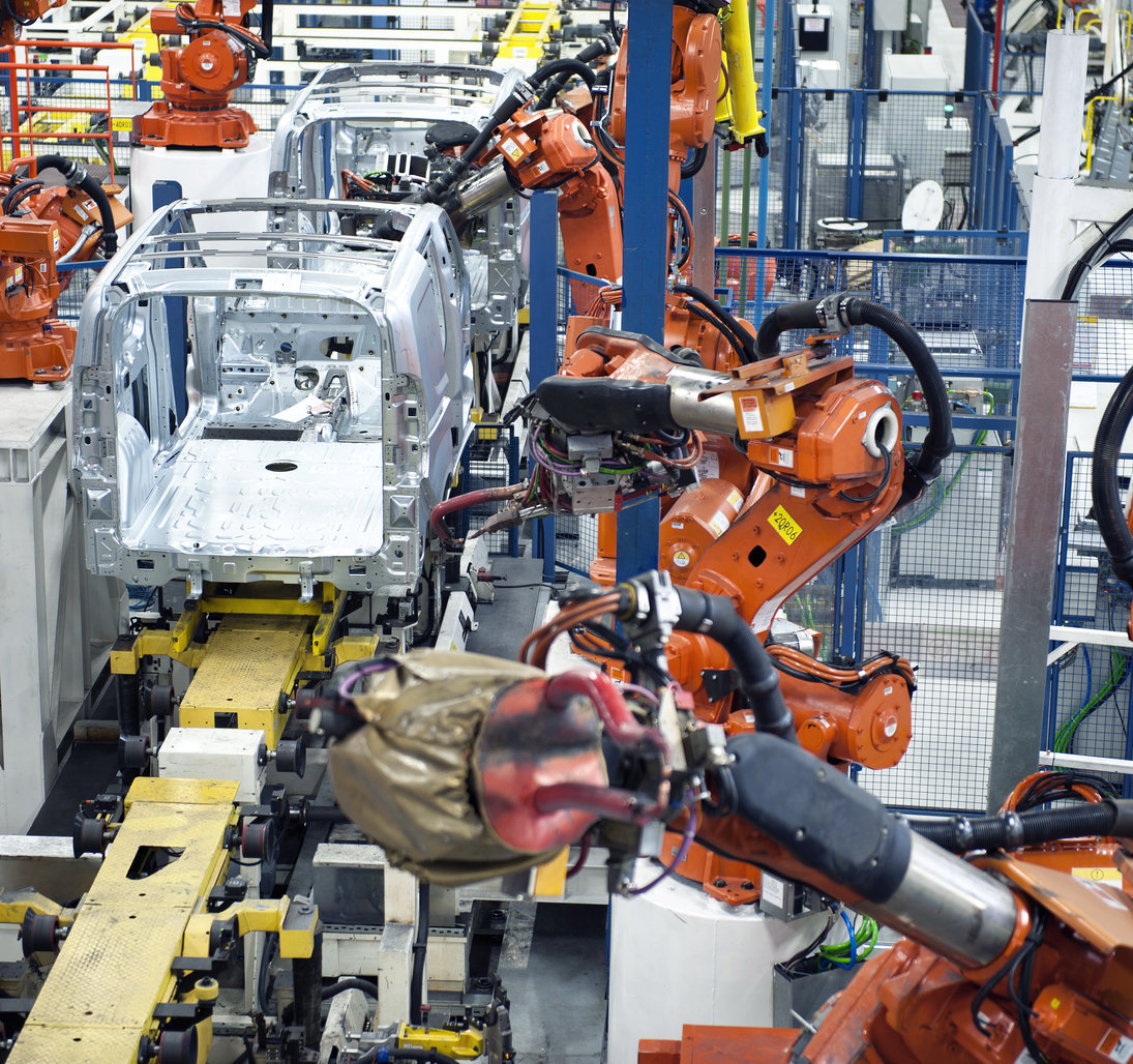
Waygate Technologies' heritage brand Phoenix began in 1999 as a pioneer in microfocus electronics inspection such as PCBA and BGA. Since the invention of the first industrial nanofocus X-ray tube in 2002, Waygate Technologies has provided superior inspection solutions for the most demanding requirements of the semiconductor industry through to high throughput CT solutions for large part inspection in the aerospace and automotive sectors.
Nổi bật

Waygate Technologies provides cutting-edge industrial X-ray inspection and CT equipment, available on demand at Customer Solution Centers located worldwide. Discover how Waygate Technologies' global Customer Solution Centers make advanced industrial X-ray and CT inspection equipment accessible on demand- just click ''Learn More'' for details.
Nổi bật
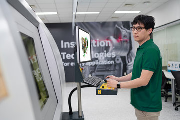
Our radiographic testing and industrial CT equipment
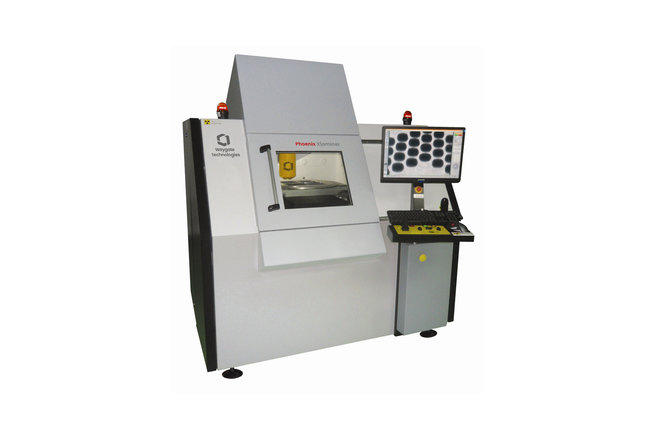
Phoenix X|aminer System
Industrial Microfocus X-Ray Inspection System
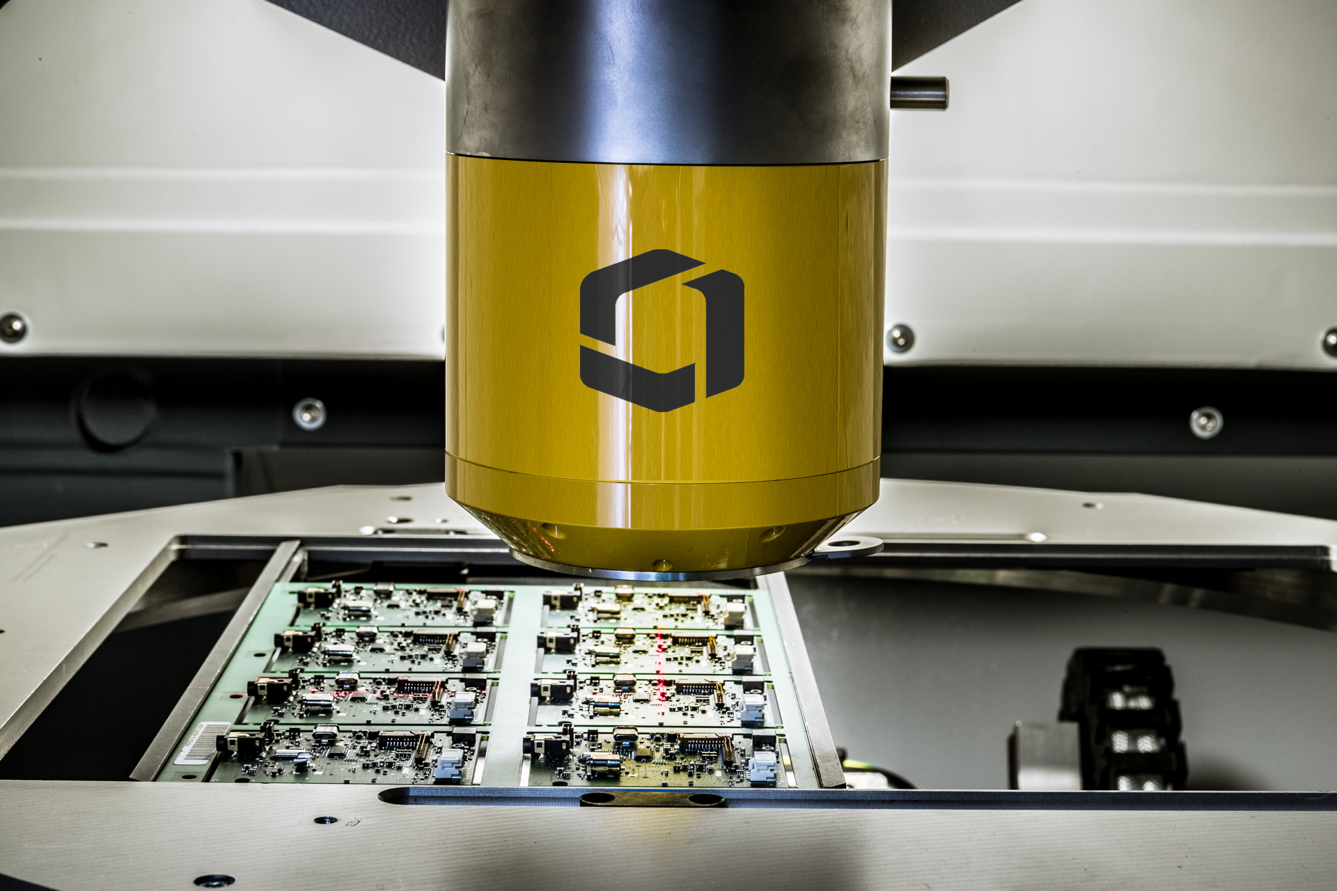
The Phoenix X|aminer is Waygate Technologies' easy to use entry-level microfocus X-ray inspection (AXI) system with strong performance that is designed for the special needs of the high-resolution inspection of electronic assemblies, components and PCBA.

Phoenix Microme|x Neo & Nanome|x Neo
Advanced non-destructive electronics inspection starts here
The Phoenix Microme|x Neo and Nanome|x Neo provide high-resolution 2D X-ray technology, Planar|CT and 3D computed tomography (CT) scanning in one system. They are ideally suited for industrial X-ray electronics inspections in process and quality control for greater productivity, failure analysis, quality of your products, and R&D.

Phoenix Nanotom® M
High spatial and contrast 3D CT resolution on a very wide sample range starts here
The Phoenix Nanotom® M is a nanofocus X-ray CT system for scientific and industrial computed tomography (microCT and nanoCT®) and 3D metrology. The system realizes a unique spatial and contrast resolution on a wide sample and application range.
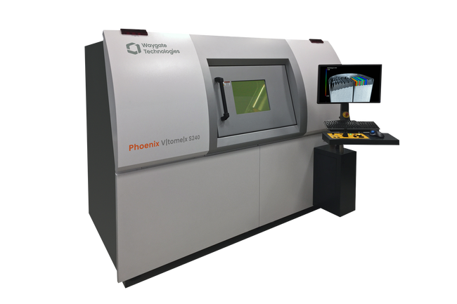
Phoenix V|tome|x S240
Industrial microCT and nanoCT Scanning starts here
The Phoenix V|tome|x S 240 is one of the few CT systems worldwide combining the highly efficient Dynamic 41 detector technology and High-flux|target — enabling high image quality as it scans much faster, or with improved accuracy, and truly revolutionizing inspection.
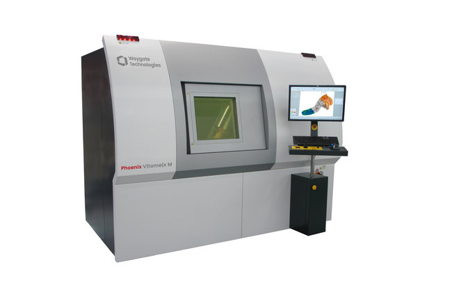
Phoenix V|tome|x M300
Premium 3D metrology and analysis with industrial CT starts here
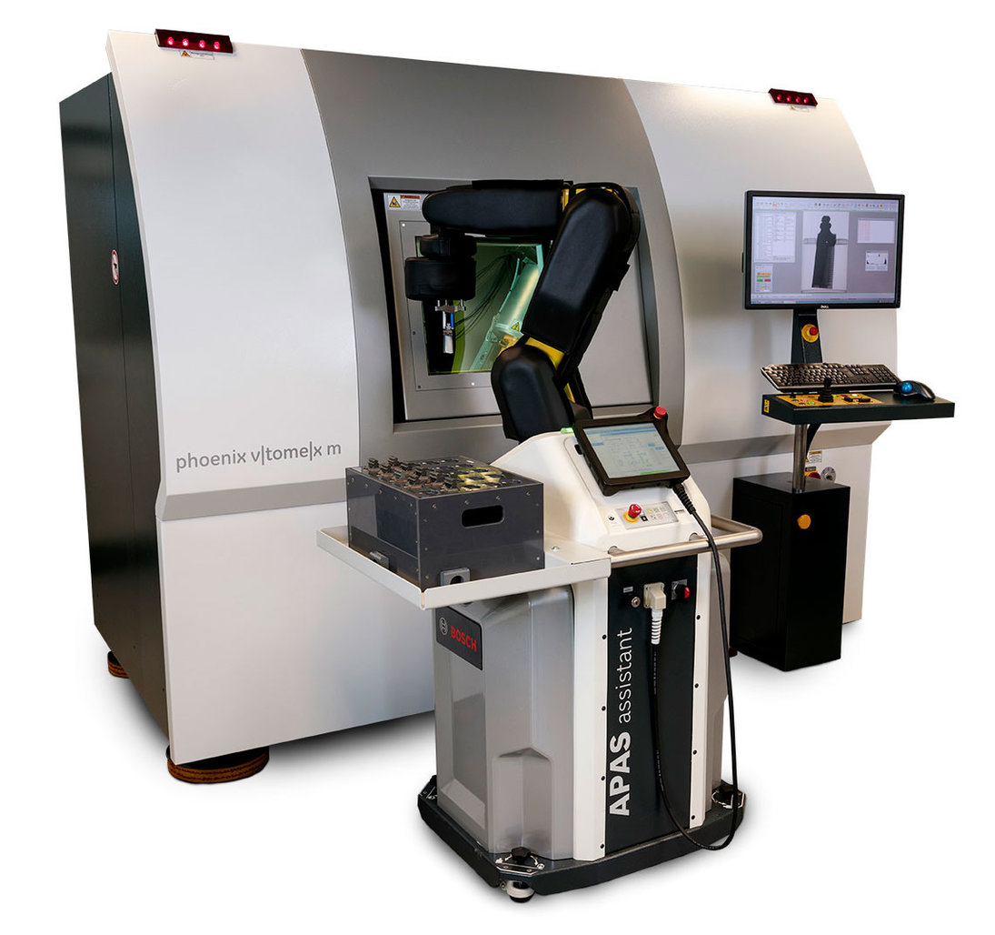
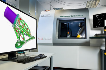
The Phoenix V|tome|x M is Waygate Technologies most versatile and precise X-ray microfocus CT cabinet system for 3D metrology and analysis. This highly productive Dual|tube scanner with its 300 kV microfocus and optional 180 kV nanofocus X-ray tubes delivers improved accuracy at unprecedented speed.

Phoenix V|tome|x M Neo
Premium 3D metrology and analysis with industrial CT starts here
The Phoenix V|tome|x M Neo is a next-generation industrial CT system, building on the success of the widely-used Phoenix V|tome|x platform with over a thousand installations worldwide. It offers remarkable advancements, including improved image results, an expanded scanning area for larger and heavier samples, variable focus detector distance, and a new cabinet design for enhanced flexibility and accessibility.

Phoenix V|tome|x C450
Compact industrial Minifocus CT Inspection starts here
The Phoenix V|tome|x C is a high performance compact industrial 450 kV Minifocus CT system for inspection and 3D metrology of a wide applications range such as large light metal castings, turbine blades, AM parts etc. The V|tome|x C450 is also available with Mesofocus tube for more resolution.

Phoenix Power|Scan HE
High Energy CT Inspection starts here
The combination of penetration power and our advanced CT features such as Scatter|correct technology make this CT system predestined to scan extremely large, heavy and high absorbing complex parts and assemblies with unmatched speed, precision, and ease of use — enabling faster, more precise inspections.
Where radiographic testing and NDT solutions matter

Automotive
Inspection & NDT solutions for the automotive industry
Why choose Waygate Technologies
Over 120 Years of Experience
With a deep-rooted history in Non-Destructive Testing (NDT), Waygate Technologies has over a century of experience in delivering reliable, high-quality inspection solutions across multiple industries.
Flexible Industrial CT Scanning
Waygate Technologies’ CT systems offer flexibility for inspecting both small parts and large components. With Dual|tube configurations and the ability to scan up to 2000 mm in diameter, our solutions deliver precise results across industries like aerospace and automotive.
Maximized Efficiency
Waygate Technologies’ premium CT solutions reduce inspection times from hours to minutes without compromising quality. Innovations like Scatter|correct technology and the Dynamic 41 digital detector deliver precise, high-resolution results to your inspections.
Adaptable Solutions for Complex Environments
Waygate Technologies offers a wide range of radiographic and CT solutions, from mobile X-ray equipment to advanced 3D CT systems. These robust and efficient tools integrate seamlessly into production workflows, delivering precise inspections that help save time and reduce costs, while ensuring the highest safety and quality standards across industries.
Our product success stories
Radiographic Testing (RT)/X-ray Inspection falls under the umbrella of non-destructive testing (NDT) and is a method that examines the target sample by penetrating it with X-rays and in so doing highlights deviations in material density that can signal an imperfection that needs to be addressed.
Radiography uses X-rays and gamma-rays to produce a radiographic image of the target sample, allowing the technician to observe any changes in material thickness, internal and surface defects, and even assembly details (i.e. welds, joints, connectors) to ensure the highest levels of quality and safety in your production.
X-rays are a highly energetic form of electromagnetic radiation with a wavelength in the range of 1 nm to 1 pms, approximately 1,000 to 1,000,000 times smaller than the wavelength of light. Due to their being highly energetic, X-rays are able to pass through materials that absorb ordinary visible light.
Radiographic Testing (RT) can be achieved via X-rays or gamma rays. X-rays are produced via an X-ray tube, while gamma rays are produced by the introduction of a radioactive isotope.
These radiation sources use much higher energy levels than those associated with electromagnetic waves.
Because of the ionizing radiation involved in radiographic testing, it is important to make sure proper safety guidelines are communicated and adhered to so as to prevent exposure.
In this regard, X-rays generated by a X-ray tube can be safely switched off. Isotopes are more ergonomic to carry but they cannot be switched off. They emit immense radiation and must be safely shielded and stored when not in use. Failure to do so can lead to long-term damage to health.
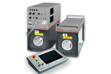
In stationary application X-ray inspection systems consist of a radiation safe enclosure, the radiation protection cabinet, containing, in linear alignment of the X-ray tube and the X-ray detector. A remotely controllable manipulating unit allows the user to position the sample within the beam. The final X-ray image is displayed on a monitor for computerized image processing. In addition, the X-ray system may be outfitted with a fully automated sample inspection. The X-ray image shows object features based on differences in material density.
In field application the sample will not be manipulated. The X-ray source and Detector/Film/Image Plate will be positioned close to the sample. There is also no radiation protection cabinet. The operator controls the X-ray source from remote and in a safety distance of more than 20 meters.
Part of the X-ray spectrum is absorbed when passing through an object. The thicker or higher in density the object, the more X-rays are absorbed and do not pass through. Those X-rays that pass through the object strike a Detector/Film/Image Plate where an X-ray image is created. This image is made up of different shades of gray depending upon the intensity of the incident rays: Using a Detector or Image Plate parts of the object that are thicker or materials that are higher in density, such as iron, copper, and lead, appear darker than less dense materials such as plastics, paper, or even air.
Film is processed in a darkroom - much like typical photographic film - and the various degrees of radiation captured by the film are represented as different values of white and black. X-rays not absorbed by the target sample will cause exposure of the radiographic film detector. These areas will appear dark (in contrast to detectors). Areas that absorbed higher levels due to higher absorbing or more dense material will appear light.
In this way, regions of your target sample where uniform density has been changed by imperfections, such as porosity, cracks, or misalignment will appear with Film as dark and with Detectors/Image Plates as light lines/spots, thus making it easier for a skilled technician to detect.
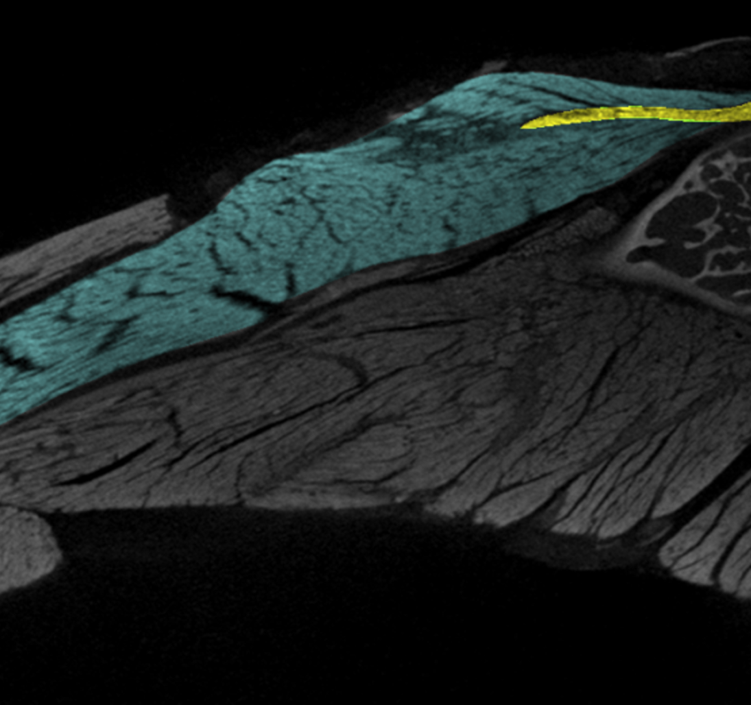
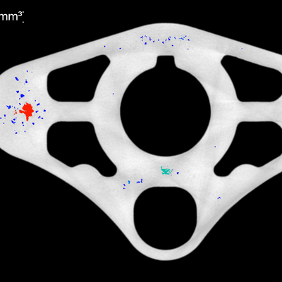
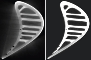
Computed tomography provides a three-dimensional, spatial image of the object under inspection which can be virtually sliced in any direction. The CT-image shows different materials or density deviations (e.g. porosity) as different shades of gray (or as different colors).
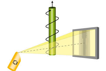
To generate a three-dimensional image, a large number of two-dimensional X-ray images (or slices) are taken around a single axis of rotation (360°). These X-ray images are then reconstructed as volumetric representations of structures (3D) using a complex reconstruction algorithm.
With 2-dimensional (2D) radiography, an image is taken from one direction, so that an integral gray value is obtained over the sample thickness. This gray value can provide information about a possible defect in this two-dimensional image, but not at what depth it is and whether for example, it can be one or more pores in a row. Additionally, dimensional measurements are limited to edges that are in the orthogonal direction to the beam.
In a three-dimensional (3D/CT) analysis, the part is irradiated from a variety of directions (360°) and produces a large amount of 2D images. These images and their respective gray values per pixel are then reconstructed by an evaluation software so that these many images can be used to calculate a three-dimensional volumeof the sample and the internal structures as well as defects.
The 3D/CT analysis therefore requires more time and data than the 2D analysis but is much more informative than the 2D analysis in terms of defining specimen dimensions and defect assessment.
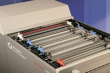
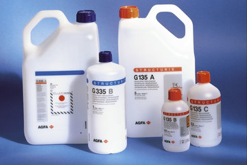
It all began with X-ray film and film is still mostly used today, especially in mobile field applications (pipelines, shipbuilding, refineries, etc.). The exposed X-ray film is then developed using a series of chemical baths and dried so that the film can then be evaluated directly with the human eye or converted into a digital copy using a film scanner and evaluated using computer software. Film is easy to use in the field and can be attached to a wide variety of specimen dimensions. The disadvantage is that X-ray films require expensive silver and can only be used once.
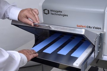
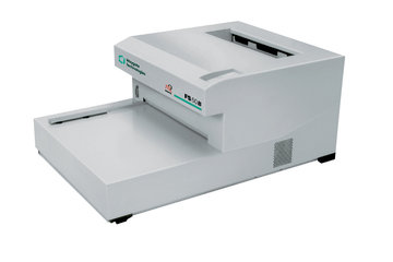
Here, Phosphor Image Plates with Computed Radiography (CR) offer an attractive alternative to film, as they can be flexibly attached to the specimen in a similar way to film and can also be used again many times for further inspections after they have been read in a scanner and converted into a digital image.
Film and Image Plates can only be used for 2D analysis.
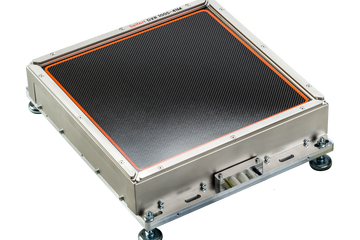
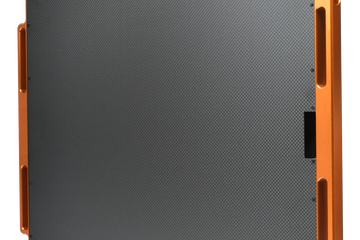
With the help of detectors (DR – Digital Radiography), 3D examinations can be carried out in addition to 2D examinations. Detectors are mostly used in stationary X-ray systems and bunkers. With them you save the time of developing the film and scanning the film/image plate, as the photons directly generate signals in the detector, which can be recorded at the same time on the computer and evaluated later. Detectors are also subject to wear, but depending on the usage parameters, a large number of examinations can be carried out at high speed in 2D and 3D.
Detectors are also used for 2D examinations as portable units in the field. The development of flexible detectors enables positioning directly on curved component surfaces (similar to film) and supports this increasing field use.
Which of the two radiography methods (2D or 3D) is more suitable depends on the respective application.
For example, during part development and initial production trials, CT analysis could help uncover design or production process vulnerabilities. If these challenges have been solved, it could also make sense to examine samples with CT in series production or, even after solving these hurdles in series production, to examine the parts with the faster but less informative 2D radiography and to sort out parts if limit values are exceeded or to inspect these individual parts separately again with CT before a decision is made regarding its further use.
For this reason, it is very advisable to take a closer look at which parts you want to make which details (smallest defects, dimensions, layers, etc.) and at what intervals visible.
Tests should also be carried out to determine the inspection parameters for the best or necessary accuracy and speed.
Since this method involves transmission and therefore X-rays still need emerge on the side opposite the beam source after they have fully penetrated the specimen and a reaction must occur on a detector, film or imaging plate, a certain acceleration energy is primarily required. This acceleration energy is measured in kilo (keV) or mega electron volts (MeV). This energy is necessary for generating the X-rays. The higher the excitation voltage, the more kinetic energy the photons generated have to get through the specimen. The denser a material is or the thicker a specimen is in the direction of radiation, the more acceleration energy is required.
If the X-rays come through the specimen, they generate signals in the detector, chemical blackening in the film and a chemical excitation of an image point in the Image Plate which later provides information about Gray values for the radiograph/image and make it evaluable.
Now it is also interesting how quickly enough photons arrive on the side of the detector/film/image plate for an evaluable image. This can be influenced by the current(mA) used to excite the X-ray photons. The greater this current strength, the more photons are excited in a certain time and can also be used to create images faster.
The distance between the radiation source and the detector/film/image plate is also important. The larger this focus-detector distance (FDD), the smaller the signal/amount of photons per unit area which requires longer exposure/inspection cycles, since the photons propagate in all spatial directions.
Which smallest resolution can be created in the subsequent image (2D pixels, 3D/CT voxels) then depends on three things:
- The smaller the X-ray focal spot size the higher the potential sharpness on detector side but in parallel the smaller focal spots normally have lower power/current on max. voltage reducing the inspection speed
- Pixel size (the smaller the better for smaller resolution) of the detector or image plate or, with film, the smallest visible chemical blackening that can be resolved by the human eye or a film scanner (pixel size)
- Geometric magnification (M=FDD/FOD while FDD represents the distance between the X-ray source and detector and the FOD represents the distance between the X-ray source and the object/specimen), in which, for example, the specimen is placed exactly in the middle between the X-ray source and detectors/film/image Plate is positioned and thus magnified twice, while no magnification is obtained if the detector/film/image plate is directly in contact with the test specimen
Ultimately, the sensitivity of the image creating sensor is important:
- Detector and image plates chemical/physical speed to generate the Gray value information, which influences the process speed especially in 3D analysis.
- Film the chemical speed and grain structure to create the required level of detail and contrast.
Due to the many influencing parameters, tests should be carried out to determine which inspection solution is best suited for the inspection task.
Radiographic testing (RT) in welding is a non-destructive testing (NDT) method used to inspect the quality and integrity of welds. It involves using X-rays or gamma rays to penetrate the weld and surrounding material, producing an image (called a radiograph) that shows the internal structure of the weld. This image helps identify any defects that may be present within the weld, such as:
• Porosity: Small gas pockets trapped in the weld
• Cracks: Fractures or splits in the weld
• Inclusions: Foreign materials trapped inside the weld
• Incomplete fusion: Areas where the weld metal has not fully fused with the base metal
• Undercut or underfill: Areas where the weld does not completely fill the joint
In welding, radiographic testing is used to ensure the weld meets safety and quality standards without causing damage to the welded structure. This is critical in industries like aerospace, construction, and manufacturing, where the strength and reliability of welds are essential for safety and performance.
Other services

NDT software
Industrial ultrasonic testing

Robotic inspection


